AVIS can be installed in the vehicle section \ parking lot access section line. Vehicle from walking line through the detection area, ground system unattended, can obtain the vehicle key components 3D point cloud and 2D image data, intelligent analysis to achieve automatic detection, including
Product Description
AVIS can be installed in the vehicle section \ parking lot access section line. Vehicle from walking line through the detection area, ground system unattended, can obtain the vehicle key components 3D point cloud and 2D image data, intelligent analysis to achieve automatic detection, including: wheel polygon online detection system (wheel polygon problem detection; tread surface abrasion problem detection; wheel rim thickness, rim height, tread surface abrasion, rim vertical abrasion, wheel pair inner distance, wheel diameter automatic measurement ); pantograph dynamic detection system (skid plate remaining thickness, centerline offset, working position contact pressure); vehicle 360° dynamic image intelligent detection system. Reduce the labor intensity and difficulty of manual inspection, improve work efficiency, reduce labor, improve the quality of vehicle maintenance operations, operational efficiency, operational intelligence level.

1 Equipment Overview
The wheel polygon online inspection system adopts online automatic detection for vehicles. When the vehicle passes through the inspection area, it can obtain the 3D point cloud data of wheel circumference rim and tread surface, and realize automatic detection after intelligent analysis. It includes automatic detection of wheel polygon problem, automatic detection of tread surface abrasion problem, automatic measurement of wheel rim thickness, rim height, tread surface abrasion, rim vertical abrasion, wheel pair inner distance and wheel diameter.
The system adopts a pattern projection three-dimensional sensor, stitching images of different arc segments of the same wheel by 3D point cloud stitching technology, and accurately processing the stitched images by intelligent algorithms to recover the whole circumference state of the wheel tread being detected, realizing the detection of wheel polygon problems.
2 Main Structure and Functions
The online wheel polygon detection system consists of a basic detection unit, an equipment room and a control room.
2.1 Basic Inspection Unit
The basic inspection unit includes wheel pair shape detection module, video image abrasion monitoring module, vehicle number identification module and system wake-up module, whose main function is to obtain the original image data of wheel pair shape and tread defects.
1) Wheel pair profile detection module
The wheel pair profile detection module includes multiple sets of pattern projection 3D sensors set up along both sides of the track, which can realize wheel polygon detection, tread surface abrasion detection, wheel pair key profile dimensions (including tread surface abrasion, wheel rim thickness, Qr value, wheel diameter, wheel pair internal distance, etc.) measurement, etc.
The pattern projection 3D sensor is composed of light source and 3D sensor. The light source adopts high-speed flash light source (visible light) which is harmless to human body and so on, and it can be used with the sensor to achieve fast, stable and high-precision point cloud acquisition. The equipment is centered on the wheel-rail contact point and arranged with multiple groups of pattern projection 3D sensors, as shown in the figure below.

The system can obtain the 3D point cloud data of wheel rim and tread surface, and obtain the accurate surface of wheel through a series of processing based on the 3D point cloud data of wheel circumference, and compare the surface with the standard model obtained from modeling for deviation analysis, and realize the detection of wheel polygon problems and wheel rim tread surface defects. This is shown in the figure below. At the same time, small interval section detection is performed on the precise surface of the wheel to achieve automatic detection of key wheel geometry dimensions.

2) Video image scuffing monitoring module
Video image scrub monitoring module consists of several sets of video monitors arranged at equal intervals along the track, and the monitoring video images collected by the video image monitoring module will be presented at the user terminal, which is convenient for the relevant personnel to observe and judge the scrubbing situation of the whole circumference of the wheel tread through the user terminal.
3) Car number identification module
Car number recognition module is an optical non-contact car number recognition system, mainly composed of trackside integrated image acquisition module, car position trigger module, analysis host and other parts, used for automatic recognition of rail transit vehicle number and direction of travel, with the advantages of fast recognition, accurate and reliable recognition results.
4) System wake-up module
The system wake-up module can accurately detect the real-time position of the wheels and judge the approaching and departing vehicles at the same time to wake up the system and carry out the trigger control. The equipment adopts inductive wheel detection sensor, which is installed on the rail by means of card mounting to meet the vehicle and equipment limit standards.
2.2 Equipment room
The equipment room is equipped with field control subsystem, data acquisition subsystem, data processing subsystem, and main controller monitoring subsystem; the equipment room is equipped with data acquisition subsystem and data processing subsystem to collect and process the measurement signal of the basic detection unit in real time and form the detection results; the main controller monitoring subsystem is configured to realize the communication with the host in the control room, such as receiving control commands from the host in the control room, sending status information and detection results to the host in the control room. By configuring the main controller monitoring subsystem to achieve communication with the host computer in the control room, such as receiving control commands from the host computer in the control room, sending status information and test results to the host computer in the control room, etc.; by configuring the site control subsystem to achieve the functions of controlling the monitoring equipment and processing the monitoring signals on site.

2.3 Control Room
Control room is located in the vehicle section DCC, control room configuration operation console, analysis server, terminal display, database, data comprehensive analysis and management software. The equipment can realize comprehensive data analysis, display wheel shape and rim tread surface condition in 3D panoramic mode, digitally display various testing parameters, and provide alarm function for exceeding the limit of measurement results. At the same time, it provides equipment status self-test management, data input/output interface, and data network upload management. The system software is reserved for networked ports, which can be connected to the vehicle maintenance operation management system.

The control room equipment can be equipped with UPS power supply to ensure normal operation of the equipment and normal data storage in case of external power failure.
3 Operation flow
No vehicle through the detection interval, the system is in standby mode, and through the wake-up module real-time monitoring of the vehicle in and out of the situation, the following is the vehicle into the detection interval after the workflow.
(1) vehicle into the detection interval, wheel dynamic image detection system automatically from the standby state to open state.
(2) the vehicle into the detection area, the basic detection unit automatically online real-time collection, the collected data transmitted to the detection data processing subsystem through the network.
(3) the vehicle out of the detection area, the system is turned off, reset, back in the standby state.
(4) data processing subsystem for image data processing, synthesis, and the measurement results and "alarm threshold standards" for comparison, to give a warning of the near limit.
4 Main technical parameters
1)Basic technical parameters
☆ train passing speed: 3~25km/h.
Total power: 20kw.
Working voltage: three-phase five-wire system AC380V.
Control voltage: AC220V/DC24V.
2) Equipment detection accuracy
☆ 3D point cloud point spacing: <0.3mm
☆Wheel pair profile detection range: full wheel circumference (full circle 360°)
☆Wheel rim tread profile section interval: <5mm (wheel circumference direction is measured once at an interval of 5mm)
Measuring range of wheel rim height: 25~40mm
Measurement error of wheel rim height: ±0.3mm
Rim thickness measurement range: 20~40mm
Measurement error of rim thickness: ±0.3mm
Measuring range of the inner distance of the wheel pair:1345~1365mm
Measuring error of inner distance of wheel pair:±0.6mm
Wheel diameter measurement range:750~1150mm
Wheel diameter measurement error:±0.6mm
Qr value measurement range:0~13mm
Qr value measurement error: ±0.6mm
☆ wheel rim tread surface defects detection range: full wear parts (including wheel rim, tread surface)
Abrasion depth measurement range: 0~15mm
Abrasion depth measurement error: ±0.3mm
☆Wheel diameter runout detection accuracy: ±0.1mm
☆ Peeling, falling block, grinding pile detection size: <10mm x 10mm x 0.5mm
☆Density of point cloud on the surface of wheel rim tread: ≮50 points/cm2
5 Other features
1)Sensor independent protection function
The pattern projection 3D sensor is equipped with a corresponding wavelength filter to ensure that the ambient light has no effect on the system and has the function of adapting to the ambient light, and the pattern projection 3D sensor itself has the function of dustproof and waterproof.
1 Equipment Overview
The pantograph dynamic detection system is used for vehicle pantograph and roof detection.
When the vehicle passes through the detection area of the pantograph dynamic detection system at a specified speed, the system's pattern 3D detection module and image recording module collect pantograph point cloud data and roof image respectively to achieve roof pantograph size information detection and roof state monitoring.
The pantograph dimensional information detected by the detection system includes pantograph wear, centerline offset and pantograph working position contact pressure.

Pantograph dynamic detection system
2 Equipment Composition
The pantograph dynamic inspection system is composed of pattern 3D inspection module, mounting bracket, light source, image recording module, control cabinet, remote viewing terminal, etc.
Pattern 3D detection module and light source are installed on the mounting bracket at the rail side for measuring 3D point cloud data of vehicle pantograph, which is the core component of the whole device. Two sets of pattern 3D detection modules collect pantograph point clouds from the upper and lower sides respectively to complete the detection of the whole pantograph, and the pattern 3D detection modules and light sources work together and are controlled by a unified trigger module.

Pattern 3D detection unit
The roof state detection module is located on the platform on one side of the inspection shed, and consists of LED light source and camera, which is controlled by the system control unit to work according to the incoming vehicle state.

Roof image detection module
3 Equipment features
(1) The inspection system adopts non-contact measurement method (pattern 3D image processing system), and the whole device inspection has no contact with the vehicle throughout.
(2) Digitalization of measurement results: the 3D pictogram detection unit detects the 3D point cloud data of the pantograph under test, and calculates all parameter values of the pantograph through the point cloud data.
(3) Full record of roof state: The roof state monitoring unit consists of a high-speed industrial camera and a matching LED fill light source, which can monitor the roof state throughout the whole process, and monitor the state of roof foreign objects and key roof parts through the roof panorama. It provides alarm prompting for the wear and tear over limit, the loss of carbon skid and the deformation or falling off of key roof parts.
(4) Simple and intuitive operation: The testing device adopts Windows Form for human-computer dialogue, and various testing status and data can be easily displayed, stored, queried, analyzed, printed and other functions, and the operation is intuitive and flexible.
(5) testing device software to implement a hierarchical approach to rights management, including operator rights and administrator rights. The operator only supports basic operations, such as testing, saving, printing, etc.; the administrator supports all functions, such as user registration management, testing record management, etc.
(6) detection device has a strong anti-interference ability, the external lighting, window sunlight and other circumstances have no effect on the detection, and has a state self-test and fault alarm function.
(7) integrated detection device, visual sensor and data transmission device installed in one, the equipment power cord and data transmission line through the aviation plug and detection device connected, easy to install and maintain.
(8) Two sets of graphic 3D inspection units that can complete all the inspection items of the pantograph, no need for overhead calibration and other operations, greatly reducing the application time of the skylight point; equipment maintenance and maintenance is convenient, if the graphic 3D inspection unit failure, direct replacement can be.
(9) After the vehicle passes through the testing equipment, the pantograph testing results are calculated directly and saved automatically, supporting the printing of results. After the pantograph wear exceeds the limit, alarm information is given in time for manual verification.
(10) detection system through the network interface and other systems connected to provide TCP/IP communication, UDP communication, Web Service communication, http Rest service way communication and other communication methods for users to choose. In the local user can also export the test results through the USB interface to the data, in the remote end can be directly through the web form query operation.
4 Equipment principle
The pantograph dynamic inspection system uses two sets of pattern 3D inspection units to reconstruct the 3D point cloud data of the pantograph surface, and obtains the relevant inspection parameters of the pantograph by processing the point cloud data.

Pantograph point cloud data

Calculation of residual thickness of slide plate
The system obtains the pantograph 3D point cloud data through photography, and calculates the pantograph centerline deviation value through the point cloud data. The system analyzes the pantograph 3D point cloud, extracts the coordinates of the key points of the crook from it, calculates the distance from the corner of the bow to the track center through the corresponding algorithm, thus fits the pantograph centerline, calculates the vertical distance between the pantograph centerline and the track center, i.e. the deviation (offset) of the pantograph centerline relative to the track center, and analyzes and judges the deformation of the crook through the extracted coordinates of the crook. As shown in the following figure.

Measurement principle of centerline offset of pantograph
The testing equipment is measured based on the relationship between the contact pressure of the pantograph on the contact network and the height at which the contact network is lifted as a definite relationship (the only relationship between elastic force and displacement). Therefore, when the pantograph passes through the detection position, the pressure at the contact position can be measured indirectly by measuring the lift of the contact line. This system calibrates the relationship between the contact force and the lift of the contact line at the time of installation, and then compares the pressure on the contact line corresponding to the lift in the calibration data as the contact pressure.

Principle of contact pressure measurement
Pattern 3D detection module adopts pattern 3D image processing technology, and each detection module contains two high-speed industrial cameras, data transmission module and high-speed flash source.
The roof state monitoring unit consists of high-speed industrial camera and matching LED fill light source, which can monitor the roof state throughout the whole process, and monitor the roof foreign objects and roof key parts state through the roof panorama.

Cabinet composition
Detection device on the abnormal alarm, and display to the monitoring terminal interface, the operator can intuitively view the size data and images, to exceed the limit of the vehicle to confirm, and can mark the location, enter the manual judgment records, the final determination of information will be saved to the database, and can be distributed through the network on the terminals to achieve the vehicle data and image information view.
5 Technical parameters
1) Use environment.
Ambient temperature: -20℃~+60℃
Relative humidity: the highest relative humidity is not more than 98%
Altitude: not more than 3700m
Other: no flammable, corrosive gases
2)Detection conditions
Detection of vehicle speed: < 15km / h range of uniform speed
The system can work continuously after starting, two trains through the interval time: > 5min
3) Equipment parameters
Control room power supply: AC220V ± 10% (50Hz), 2kW
Data processing time: ≤2 min
Slip sheet wear detection accuracy: ± 0.5mm
Sliding plate effective detection length: 1000mm
Pantograph centerline deviation detection accuracy: ±3mm
Pantograph centerline deviation detection range: ±400mm
Pantograph working position contact pressure detection accuracy: ±5N
Contact pressure detection range: 0~200N
Resolution of observation of foreign objects and parts on the roof of the vehicle: 3mm
6 Equipment protection
1)Protection against wind, frost, rain, snow and dust
Multi-layer anti-rust treatment is applied to the installation bracket to ensure that it will not rust even under harsh outdoor conditions. Other selected electrical components meet IP54 and above protection standards, and can still work normally under wind, frost, rain, snow and dusty conditions. Pattern 3D detection module shell body using high-strength magnesium aluminum alloy whole material processing, wall thickness ≥ 4mm, built-in reinforcement; due to the use of whole material processing, to avoid the potential risks of ordinary cast aluminum such as air holes trachoma; good heat dissipation, high stability of equipment, long service life; the overall protection level up to IP65.
2)Protection against high temperature and high humidity
The electrical components of the equipment are selected with high standard devices, and comprehensively, the working environment temperature range of the equipment is -20℃~+60℃, and the relative humidity of the working environment is up to 98%, which can fully adapt to the high temperature and high humidity working environment.
3)Protection against lightning
In order to cope with the threat of outdoor lightning to the equipment, a number of lightning protection measures are equipped, such as power supply lightning protector, grounding lightning protection box, network signal lightning protector, video signal lightning protector, etc., to ensure the safety of the equipment in lightning weather.
1 Equipment overview
Vehicle 360 ° dynamic image intelligent detection system is installed in the vehicle section \ parking lot access section line, vehicle since walking through the detection area, ground system unattended, can obtain the vehicle key components 3D point cloud and 2D image data, intelligent analysis to achieve automatic detection. Realize comprehensive monitoring and testing of the working status of the underbody walking part, vehicle side bogie, roof pantograph and other key components, and realize automatic early warning of key components missing, deformation, foreign objects and other abnormal conditions.

2 Equipment composition and technical requirements
Vehicle 360 ° dynamic image intelligent detection system according to the layout is divided into three parts: on-site detection unit, equipment room, control room.
The site detection unit is composed of gantry bracket, graphic 3D sensor, etc. The system sets up cement casting bearing foundation on both sides of the track, and installs gantry bracket on the bearing. Outside the vehicle and equipment limits, the graphic 3D sensors are arranged 360° around the body. In order to assist the work of the field detection unit, vehicle approach detection unit and vehicle departure detection unit should be set up in the front and rear of the field detection unit, respectively.

The equipment room consists of power distribution box, control box, industrial control machine, switchboard, UPS, PDU and other equipment to realize the power supply, control, data and image acquisition, analysis and processing, storage of the on-site detection unit, while communicating with the control room.
The control room consists of a console, IPC and peripheral equipment. In the control room, it realizes the setting of system parameters, monitors the operation status of the equipment and the testing process, and views, counts, analyzes and prints the testing data.
3 Main functions of the equipment
3.1 The main functions of the intelligent detection system.
(1) The system has automatic collection of visible parts of the train roof, visible parts of the car body windows, visible parts of the side walkers, visible parts of the bottom walkers, covering 360° panoramic high-density 3D point cloud and high-definition 2D images of the car body.
(2) The system adopts 3D point cloud detection technology based on the complete surface of the components to avoid splicing deformation errors.
(3) The system automatically synthesizes the 3D point cloud and 2D images, and displays them in virtual 3D form, so that users can view and analyze the vehicle parts in three dimensions.

(4) The system has the function of automatic monitoring of key parts under the subway vehicle, including the traction device, motor cover, brake pad or brake disc, gear box, axle box and other key parts, and the function of timely alarm prompting when missing, deformation, foreign objects and other abnormal problems are found.
(5) The system has the function of automatic monitoring of the key parts of the bogie on the side of the subway vehicle, and promptly alarming and prompting when abnormal problems such as missing are found.
(6) The system has the function of automatically rejecting the false alarm caused by water stain, light, shadow and other interference, which can be achieved by using the joint warning method of three-dimensional image and two-bit image to reject, or by using color imaging to filter the interference caused by water stain, light and shadow directly through the feature algorithm determination.
(7) the system has a subway vehicle roof, side windows visible parts of the automatic monitoring function, found pantographs and other key parts of the roof deformation or fall off, the roof of foreign objects and other faults automatic warning.
(8) The system has image magnification function, and can display multi-level magnification of small parts.
(9) The system has car number and end position automatic identification, through speed detection, vehicle approach and departure detection functions.
(10) The system has the functions of lightning protection, water-proof, high-current shock prevention and grounding, etc., with anti-electromagnetic interference, anti-vibration characteristics, and can adapt to high and low temperature environments.
(11) the system has detection data storage, analysis, query, statistics and output functions; with detection data alarm prompt function.
(12) The system has remote monitoring and data analysis functions, providing B/S access interface and information data networking interface.

(13) The system can be built at the same site as the wheel pair and pantograph dynamic detection system in the wheel pair detection shed of the outgoing and incoming section lines, or it can be set up separately, installed without shed, adapted to outdoor open-air environment, and 100% resistant to sunlight interference. The bidder can provide the proposed scheme according to the attached drawing, but the bidder has the right to determine the final setting scheme, and the bidder shall not object, and the cost is included in the total bid price.
3.2 The graphic 3D sensor has the following basic performance.
(1) 3D point cloud detection technology based on the complete surface of the component, compared to laser scanning based on contour lines, no splicing deformation error, high point cloud density, no scanning interval blind area.
(2) non-laser lighting technology, high brightness photography industry light source, resistance to outdoor sunlight interference, no laser safety issues, to avoid damage to the eyes and skin (high speed must correspond to high brightness light source, high brightness laser is very easy to cause damage to human eyes and skin).
(3) The device adopts graphic 3D image processing system, high-density graphic projection irradiated parts, no dead angle detection, and subtle changes can be detected stably. By combining with a high pixel camera, a large field of view and high stability can be detected.
(4) The system has effective self-cleaning and self-protection functions, and can work around the clock without supporting protective sheds.
(5) The equipment adopts modular installation method, which makes on-site construction convenient and efficient and reduces the time of trackside operation.
(6) The gantry support required for the equipment is designed for on-site assembly mode to simplify transportation, on-site transfer and construction.
(7) Applicable to the main line, access line, maintenance depot entrances and exits and depots, etc., adaptable, easy to choose the location of equipment.
(8) Reasonable selection of component materials and design of equipment structure to avoid the impact on the track signal circuit.
4 Equipment principle advantages
(1) 2D detection technology by collecting the brightness of the surface of the components, color, analysis of its changes to achieve fault identification, judgment, and therefore very vulnerable to the vehicle itself (attached to dust, oil, maintenance chalk mark and non-uniform distribution) and the external environment of strong light interference, resulting in a large number of false alarms.

Chalk marks in the figure cause identification interference with fastener anti-loose marks or other marks
Strong ambient light causes highly reflective parts of an object to be too bright, obscuring detailed features
3D inspection technology by collecting the spatial coordinate points of the contour shape of the components, after calculating to obtain the size, location information, through the analysis of the size, location information to achieve fault identification, judgment, the vehicle surface attached layer (dust, stains, etc.) does not have the size, location and other spatial information, naturally be excluded.

(2) 2D (flat) imaging itself does not accurately reflect the position of the object far and near (distance from the camera observation point), so when the vehicle components are deformed or displaced in the near and far direction, they are not clearly reflected in the 2D photos, as shown in the following figure.

Upshot right below coupler (actual detection perspective)

Shoot at the same level as the coupler (the detection equipment cannot achieve this view Angle)
In the partial structure of the hook shown in the figure, the height difference between the bolt cap surface (red frame) and the green/yellow frame plane can reflect whether the bolt is loose or not. The left picture is the actual photo view of the equipment, which is located directly below the hook, from which the height difference between the red, green and yellow surfaces cannot be distinguished, so it cannot detect whether the bolt is loose in the red frame, unless the photo view of the right picture is taken, but the right picture view is the same height as the hook level, which the actual equipment cannot do, so the traditional 2D photo detection technology will cause leakage for such faults.
3D detection technology can measure the red, green, yellow three frame parts of the plane contour point coordinates, and then find any point spacing, surface spacing and even body spacing, and compare the plane height difference of each overtaking detection can detect the amount of bolt loosening.
(3) manual inspection of bolt loosening mainly through the anti-loosening marking line, with the accumulation of running time, the body surface (especially the bottom of the car) will be attached to dust stains, the original bare clear anti-loosening marking line will be covered, 2D detection methods naturally fail, resulting in missed reports. In this case, the necessary wiping must be done even for manual inspection. The figure below shows the effect of actual adhering dust.

The 3D detection technology obtains the coordinates of the contour points on the underbody surface of the vehicle, with its own size and position information, which can be easily compared to get the displacement of the nut.
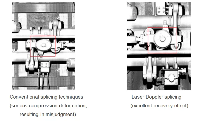
(4) Based on laser Doppler technology, it accurately detects vehicle speed and position, and improves the quality of 2D line image stitching (the basic condition for correct identification). Friends, on the other hand, use conventional rough speed measurement and positioning technology (such as ultrasonic speed measurement, magnetic steel proximity speed measurement, etc.), and the image stitching distortion is very easy to lead to misjudgment and false alarm.
5 Main technical requirements
1) Train-related.
Train passing speed: 2-25KM/h
Passing time interval: >2min
2) Working environment.
Outdoor: -40℃~+60℃
Indoor: 0℃~50℃
Relative humidity: ≤ 95%
3) Detection technology indicators and accuracy.
Underbody walking part of the visible area image resolution: ≤ 1mm / pixel
Side walking part of the visible area image resolution: ≤ 1mm / pixel
Car body, window visual area image resolution: ≤ 1mm / pixel
Roof visual area image resolution: ≤1mm/pixel
Three-dimensional image resolution: ±5mm/pixel
Key components imaging rate: not less than 99%


